GB3VHF Beacon
Technical Details
On Sunday 26th February 2006 the existing beacon hardware was replaced with
new state-of-the-art beacon hardware boasting several new RF and digital
features. The new beacon was the culmination of a year of design and
construction work by a team of four radio amateurs and included technology that
had never before been used in an amateur radio beacon.
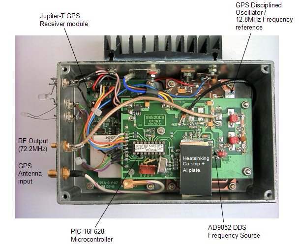
At the heart of the beacon is a direct digital synthesiser designed,
constructed and programmed by Andy Talbot, G4JNT. The direct digital
synthesiser allows the beacon to be programmed to transmit new modes. The DDS
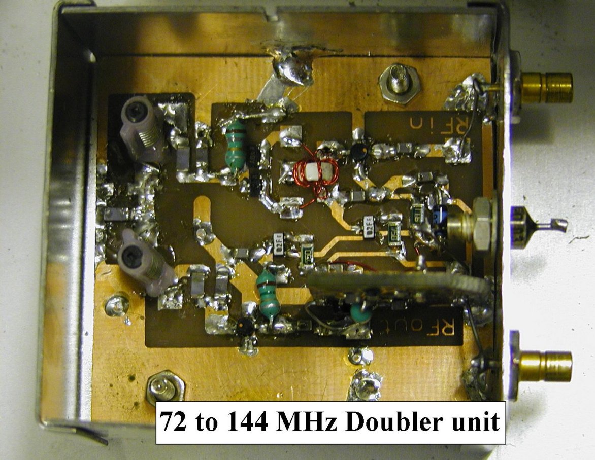
generates a signal directly at 72MHz and is L/C and crystal filtered and
doubled to 144MHz. before passing to the PA. The DDS clock source will be
locked to GPS with a short time-constant phase-locked loop, and will normally
maintain accuracy to within a few parts in 10-9 over a period of a few tens of
seconds, and better than 10-12
long term. The frequency of the CW carrier (mark) being exactly on
144.430000MHz.
The beacon sends its callsign and locator in Morse, but uses A1A (on /off)
keying rather than FSK.
To enable the beacon to be monitored at extreme ranges, the beacon also
transmits its callsign and locator using WSJT JT65B mode.
The GPS also provides for the precise timing of the keying sequence, such
that the JT65B sequence will start at every even minute past the hour for 48
seconds duration.
The Morse sequence will commence at the start of each odd minute past the
hour and last for 13 seconds
At the start of each odd minute 30 seconds past the hour, at a precisely
timed point, 140 microseconds after the UTC one-second reference as signalled
by the GPS receiver, the phase of the carrier is reversed, 28 times in total to
fill up the 30 second time slot. The result is a 1 bit/second pattern of
101010….. The BPSK mode has been incorporated to allow users to become
familiar with using precise timing methods to assist in experimentation with
coherent signal recovery, to measure time of flight information and propagation
testing.
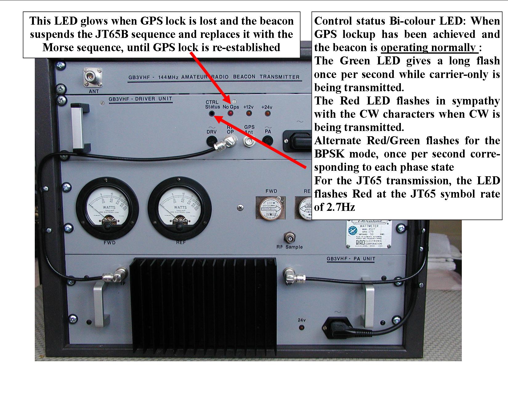
In the event of GPS lock being lost, the beacon will suspend the JT65B
sequence and replace it with the Morse sequence, until such time as GPS lock is
re-established.
Full details of this unit can be found on Andy’s website www.g4jnt.com.
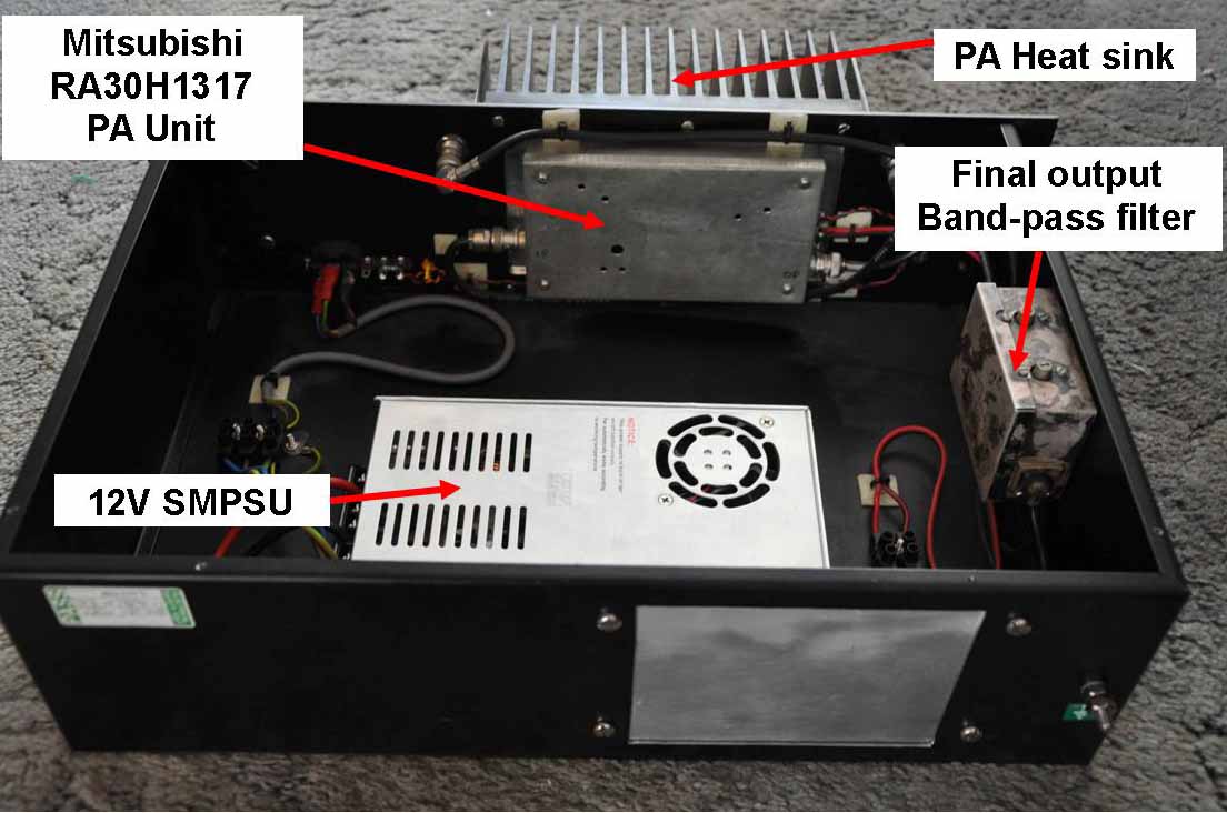
The beacon’s RF section was designed by Sam Jewell, G4DDK and relies
on a Mitsubishi RA30H1317 power amplifier module for the PA. The use of
extensive RF L/C filtering throughout and a special crystal filter at 72MHz
ensures that the beacon complies with the most stringent CEPT regulations for
transmitters operating in the VHF frequency range. Both in-band and out-band
spurious signals are suppressed to better than -70dBc. The crystal filter
ensures also that close-in noise sidebands are adequately suppressed to ensure
no interference to users listening close to the beacon's frequency, for other
beacons. The PA uses only heat sink convection cooling and no extra fan cooling
is provided or needed under any environmental conditions.
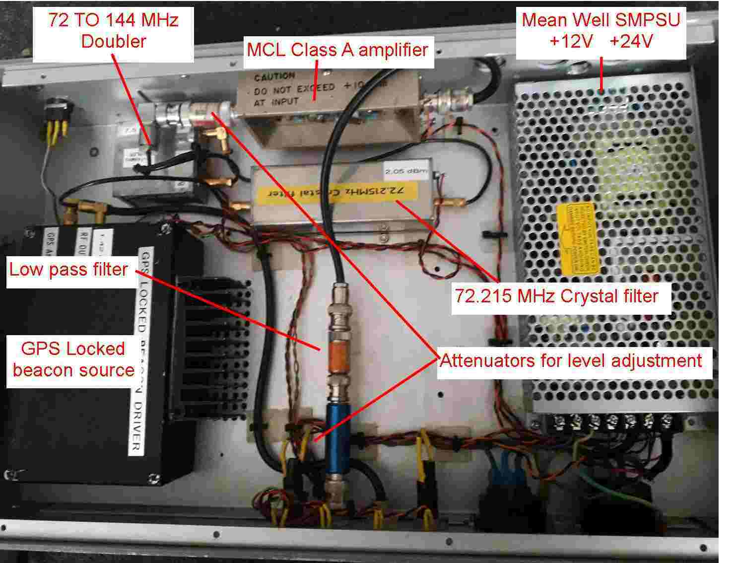
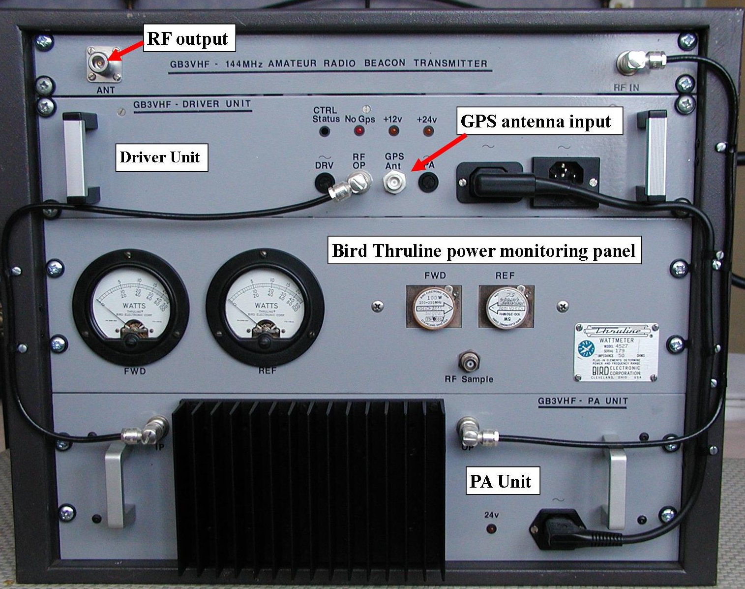
The RF output from the driver unit is 13dBm. This drives the PA unit to
produce a beacon final power output of 15dBW (30Watts). This is monitored with
a Bird Thruline power monitoring panel that shows both forward and reflected
power simultaneously.
The beacon’s orginal power supplies, delivering both 12 and 24 Volts,
were specially designed and built by David Bowman, G0MRF. The 12 and 24 volt
SMPSU for the beacon driver unit now uses a Mean Well RD-125-1224 whixh can
deliver both 12 & 24 volts at around 3.5 A each. The original 12v PSU for
the PA was a conventional linear unit. This PA PSU has now been replaced by the
same type of high grade SMPSU as used on GB3UHF which is a Mean Well
709-NES350-12 deliving up to 29A. All PSU’s use only heat sink convection
cooling and no external fan cooling is required under any environmental
conditions
Chris Whitmarsh, G0FDZ, the beacon keeper, integrated the various modules
and units, and produced the metalwork and housing facilities for the beacon.
The beacon was designed so that the driver and PA were built as separate units
to ease access and maintenance. All connections are brought to the front on the
units for the same reason. External connections to the beacon are simply mains
power, GPS antenna and the main antenna system. Like most commercial systems,
all the beacon units are built as 19 inch rack mount style, and the whole
beacon occupies a rack space of 9U.
Using beacons GB3VHF
Home GB3VHF Antenna details Receiving GB3VHF Using GB3VHF GB3VHF Installation photos GB3VHF History
GB3VHF Sponsors & Donors Send a GB3VHF reception report Donate to the beacon fund Contact the beacon keeper Service news GB3UHF Home