GB3UHF Beacon
Technical Details
The heart of the
beacon is the frequency generator based on the OZ2M next generation beacon
(NGB) system.
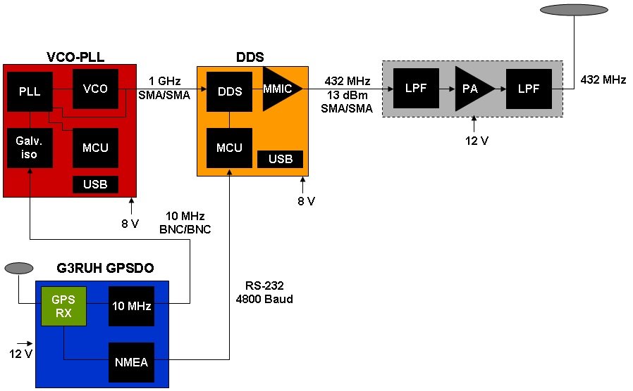
The 1 GHz PLL/VCO
synthesiser reference is a G3RUH 10MHz GPSDO (Global Positioning System
Disciplined Oscillator). This beacon includes some of the latest technology and
modulation methods.
The 1 GHz VCO/PLL
synthesiser uses an ADF4107 PLL that is controlled by an Atmel ATmega328 and a
Crystek CVCO55CX-1000-1000 ultra low noise VCO using the 10MHz GPSDO reference
and generates a signal of which the output is applied to the DDS. The DDS
generates a signal at 432 MHz by using sampling techniques of an AD9912 which
is controlled by an Atmel ATmega128A. The output at low level is low-pass
filtered (using a filter suplied by Sam Jewell G4DDK) and amplified by a
Class-A MCL RF amplifier and then level adjusted before passing to the PA. The
G3RUH PLL reference 10MHz oscillator that has an oven controlled crystal
oscillator (OCXO) which is disciplined by reference to GPS signals. A spare
10MHz OCXO (not GPS disciplined) is now kept on site for emergency use only if
the main GPSDO fails. If this is brought into use then the beacon will send
only the CW ident and a notice will appear on this site giving the current
status.
The beacon
frequency reference accuracy after warm up is better then 1010 after 30 mins with increasing
improvement in accuracy. The frequency of the CW carrier (mark) being exactly
on 432.430000MHz.
Both the
frequencies used for CW FSK and JT65B are controlled by the DDS that also takes
the GPS NMEA data to give the identification timings.
The beacon sends
its callsign and locator in Morse, and uses F1B keying (FSK) with a 400Hz
standard shift.
To enable the
beacon to be monitored at extreme ranges, the beacon also transmits its
callsign and locator using WSJT JT65B mode.
The GPS also
provides for the precise timing of the keying sequence, such that the Morse
sequence will start at every odd minute past the hour and for 14 seconds
duration and the JT65B sequence will start at every even minute past the hour
for 48 seconds duration. The keying software uses the same sequence as
GB3VHF.
In the event of
GPS lock being lost, the beacon will continue operation but with reduced
frequency and timing accuracy until such time as GPS lock is re-established.
When this occurs the JT65B sequence is suspended and replaced with the Morse
sequence until GPS lock is re-established.
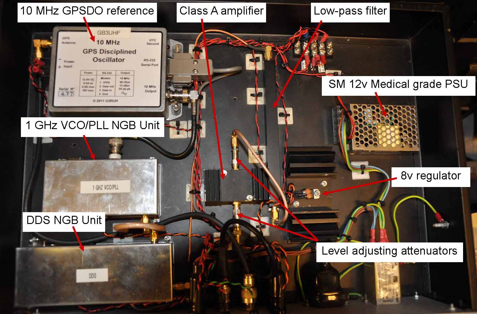
The component
parts of the driver unit
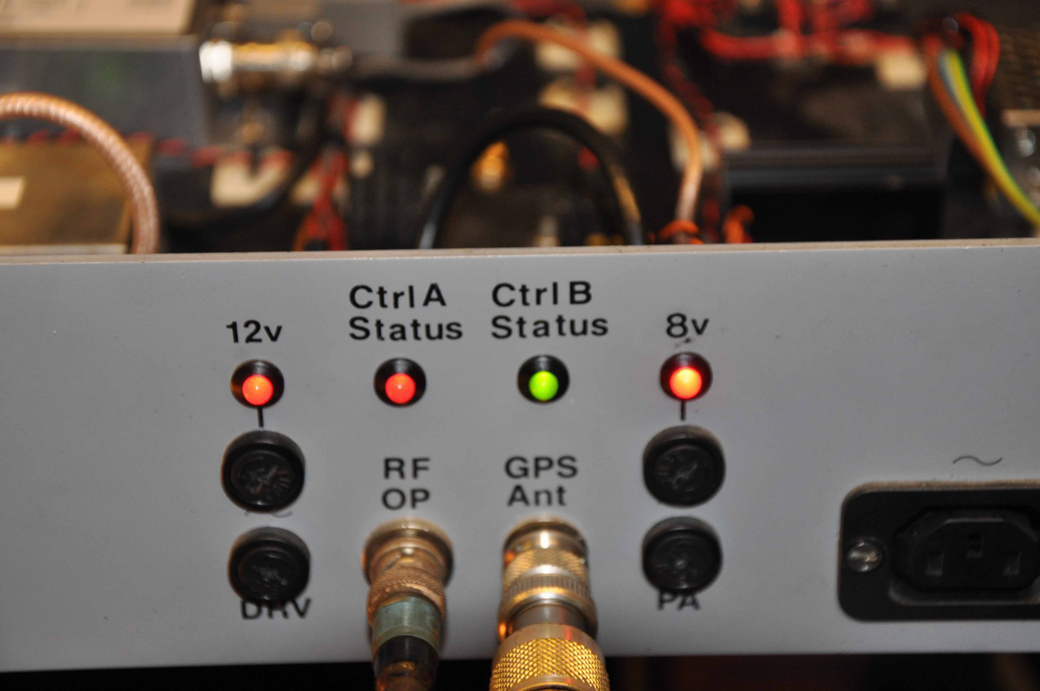
The driver front panel indicators
Full details of
the Next Generation Beacon system can be found on Bo Hansen OZ2M's website www.rudius.net/oz2m/ngnb/index.htm
The beacon’s
PA unit is based on the Mitsubishi RA60H4047 power amplifier module for the PA
with components supplied by Chris Bartram GW4DGU and Grant Hodgeson G8UBN. The
use of extensive RF filtering throughout ensures that the beacon complies with
the most stringent CEPT regulations for transmitters operating in the UHF
frequency range. Both in-band and out-band spurious signals are suppressed to
better than -65dBc. The PA uses only heat sink convection cooling and no extra
fan cooling is provided or needed under any environmental conditions.
The output from
the driver unit is 13dBm (20mW). This drives the PA unit to produce a beacon
maximum final power output of up to 15dBW (30Watts). This is further filtered
by a high power low-pass filter which was built by Sam Jewell G4DDK and then
monitored with a Bird Thruline power monitoring panel that shows both forward
and reflected power simultaneously. Finally the RF is routed through a
circulator that is used to protect the PA from high SWR fault condition and
also to prevent intermodulation occuring in the PA due to the close proximity
of the 2m beacon antennas
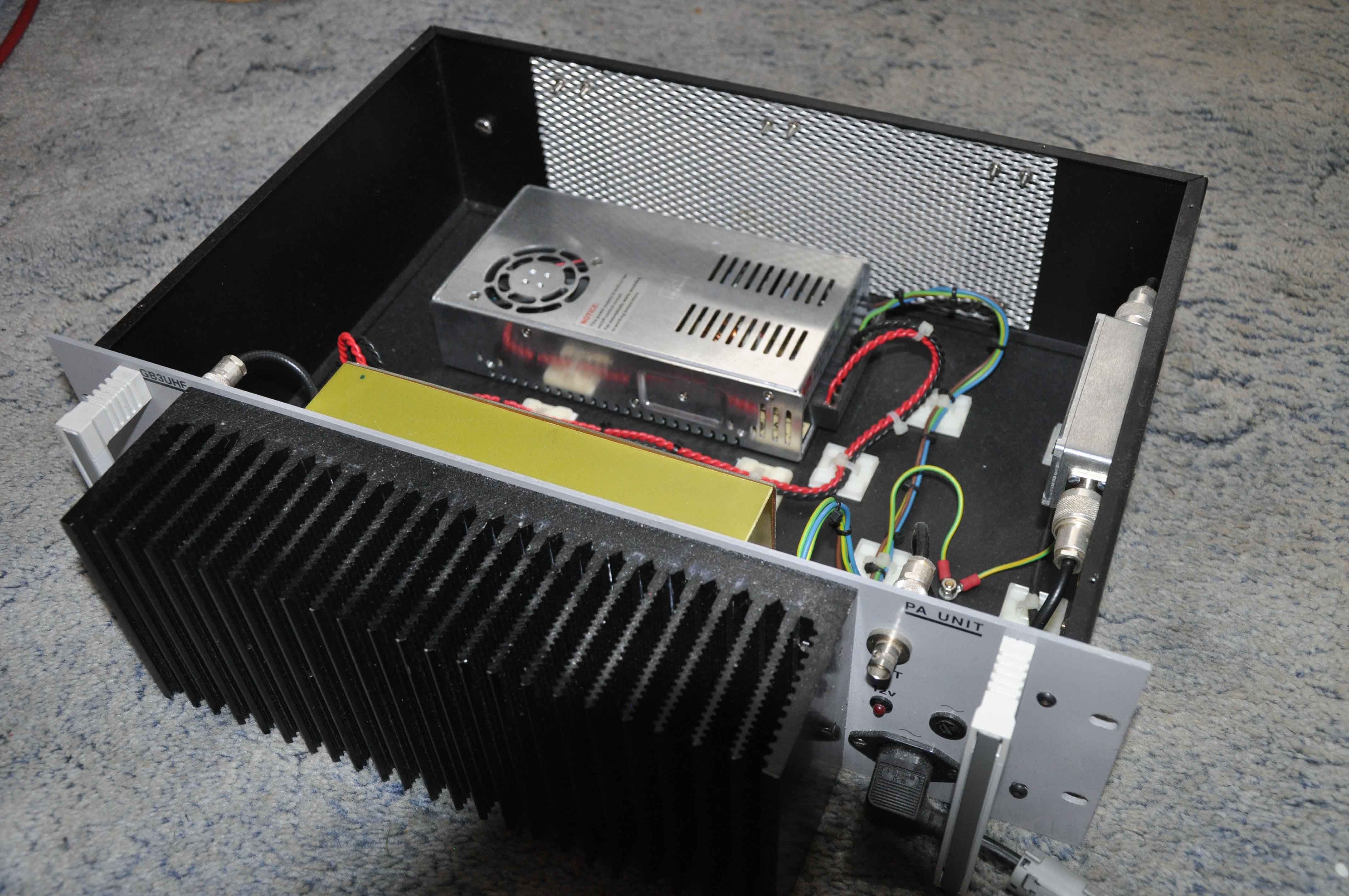
The PA unit
and PSU
The beacon’s
power supplies delivering 12 Volts, were sourced by David Bowman, G0MRF. The 12
volt PSU for the beacon driver unit uses a Mean Well RS25-12 2.1A RF proof
medical grade switched mode PSU, and is followed by a conventional 8 volt
regulator for the NGB VCO/PLL and the NGB DDS. The 12v is used for the G3RUH
GPSDO. The 12v PSU for the PA is a low noise and RF proof Mean Well
709-NES350-12 SMPSU that can deliver up to 29A . All PSU’s use only
convection cooling and no extra fan cooling is required under any environmental
conditions.
Chris Whitmarsh,
G0FDZ, the beacon keeper, integrated both the driver and PA units, and produced
the metalwork and housing facilities for the beacon. The beacon was designed so
that the driver and PA were built as separate units to ease access and
maintenance. All connections are brought to the front on the units for the same
reason. External connections to the beacon are simply mains power, GPS antenna
and the main antenna system. Like most commercial systems, all the beacon units
are built in 19 inch rack mount style, and the whole beacon which occupies a
rack space of 9U shares a rack of 18 U, together with the GB3VHF 144MHz
beacon.